
Design Guide

AGP Port Design Guidelines
R
Intel
®
855GM/855GME Chipset Platform Design Guide 179
9.2. AGP Routing Guidelines
9.2.1. 1x Timing Domain Routing Guidelines
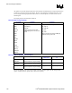
9.2.1.1. Trace Length Requirements for AGP 1X
This section contains information on the 1X timing domain routing guidelines. The AGP 1X timing
domain signals have a maximum trace length of 10 inches (pin to pin). The target impedance is 55-Ω ±
15%. This maximum applies to ALL of the signals listed as 1X timing domain signals in Table 68. In
addition to this maximum trace length requirement (refer to Table 70 and Table 71) these signals must
meet the trace spacing and trace length mismatch requirements in Sections 9.2.1.2 and 9.2.1.3.
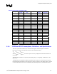
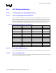
Table 70. Layout Routing Guidelines for AGP 1X Signals
1X signals Max. Length (inches) Width (mils) Space (mils)
CLK_AGP 10 4 4
AGP_PIPE# 10 4 4
AGP_RBF# 10 4 4
AGP_WBF# 10 4 4
AGP_ST[2:0] 10 4 4
AGP_FRAME# 10 4 4
AGP_IRDY# 10 4 4
AGP_TRDY# 10 4 4
AGP_STOP# 10 4 4
AGP_DEVSEL# 10 4 4
AGP_REQ# 10 4 4
AGP_GNT# 10 4 4
AGP_PAR 10 4 4
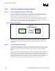
9.2.1.2. Trace Spacing Requirements
AGP 1X timing domain signals (refer to Table 68) can be routed with 4-mil minimum trace separation.
9.2.1.3. Trace Length Mismatch
There are no trace length mismatch requirements for 1X timing domain signals. These signals must meet
minimum and maximum trace length requirements.