
Design Guide

AGP Port Design Guidelines
R
180 Intel
®
855GM/855GME Chipset Platform Design Guide
9.2.2. 2x/4x Timing Domain Routing Guidelines
9.2.2.1. Trace Length Requirements for AGP 2X/4X
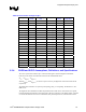
These trace length guidelines apply to ALL of the signals listed as 2X/4X timing domain signals in
Table 68. In addition to these maximum trace length requirements, these signals must meet the trace
spacing and trace length mismatch requirements in Sections 9.2.2.2 and 9.2.2.3.
The maximum line length and mismatch requirements are dependent on the routing rules used on the
motherboard. These routing rules were created to give design freedom by making tradeoffs between
signal coupling (trace spacing) and line lengths. These routing rules are divided by trace spacing. In 1:2
spacing, the distance between the traces is two times the width of traces.
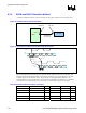
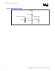
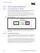
Figure 85. AGP Layout Guidelines
(Width:Space)
AGP
Controller
GMCH
1:2 Strobe to Strobe# Routing
1:3 Strobe to Data Routing
1:2 routing
6.0” max length
+/-
0.1” mismatch to
associated strobe
For 2X/4X lines in AGP interface, the max length is 6.0 inches (pin to pin) and 1:2 trace spacing is
required. 2X signals must be matched to their associated strobe within 0.1 inch. 4X signals must be
matched to both of their associated strobes within 0.1 inch. Reduce line length mismatch to ensure
added margin.
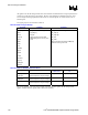
9.2.2.2. Trace Spacing Requirements
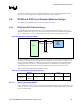
AGP 2X/4X timing domain signals must be routed as documented in Table 71. They should be routed
using 4-mil traces. Additionally, the signals can be routed with 5-mil spacing when breaking out of the
GMCH. The routing must widen to the requirement in Table 72 within 0.3 inches of the GMCH
package.
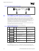
Since the strobe signals (AD_STB0, AD_STB0#, AD_STB1, AD_STB1#, SB_STB, and SB_STB#) act
as clocks on the source synchronous AGP interface, special care should be taken when routing these
signals. Because each strobe pair is truly a differential pair, the pair should be routed together (e.g. for
4x timing, AD_STB0 and AD_STB0# should be routed next to each other). The two strobes in a strobe
pair should be routed on 4-mil traces with 8 mils of space (1:2) between them. This pair should be
separated from the rest of the AGP signals (and all other signals) by at least 15 mils (1:3).