
Design Guide

AGP Port Design Guidelines
R
Intel
®
855GM/855GME Chipset Platform Design Guide 185
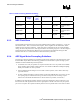
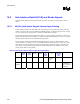
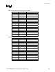
Table 75. AGP Pull-Up/Pull-Down Requirements and Straps
Signal AGP 2.0 Signal
Pull-Up/Pull-Down
Requirements
GMCH Integrated
Pull-Up/Pull-Down
Notes
DEVSEL# Pull-Up
FRAME# Pull-Up
GNT# Pull-Up
INTA# Pull-Up 3, 5
INTB# Pull-Up 3, 5
IRDY# Pull-Up
PERR# Pull-Up 2
PIPE# Pull-Up
RBF# Pull-Up
REQ# Pull-Up 1
SERR# Pull-Up 2
ST[2:0] Pull-Up 4
STOP# Pull-Up
TRDY# Pull-Up
WBF# Pull-Up
AD_STB[1:0] Pull-Up
AD_STB[1:0]# Pull-Down
SB_STB Pull-Up
SB_STB# Pull-Down
SBA[7:0] Pull-Up 1
NOTES:
1. The Intel 855GME chipset GMCH has integrated pull-ups to ensure that these signals do not float when there is
no add-in card in the connector.
2. The Intel 855GME chipset GMCH does not implement the PERR# and SERR# signals. Pull-ups on the
motherboard are required for AGP graphics controllers that implement these signals.
3. The AGP graphics controller’s INTA# and INTB# signals must but routed to the system PCI interrupt request
handler where the pull-up requirement should be met. For Intel 855GME chipset-based systems, they can be
routed to the ICH4-M’s PIRQ signals that are open drain and require pull-ups on the motherboard.
4. ST[1:0] provide the strapping options for 100-MHz PSB operation and DDR memory, respectively.
5. INTA# and INTB# should be pulled to 3.3 V, not VDDQ.
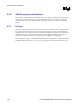
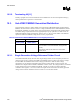
The pull-up/pull-down resistor value requirements are shown in Table 76.
Table 76. AGP 2.0 Pull-up Resistor Values
Rmin Rmax
4 kΩ 16 kΩ
The recommended AGP pull-up/pull-down resistor value is 8.2 kΩ.