
Design Guide

Hub Interface
R
188 Intel
®
855GM/855GME Chipset Platform Design Guide
10.2. Hub Interface Data HL[10:0] and Strobe Signals
The hub interface HL[10:0] data signals should be routed on the same layer as hub interface Strobe
signals.
10.2.1. HL[10:0] and Strobe Signals Internal Layer Routing
Traces should be routed 4 mils wide with 8 mils trace spacing (4 on 8) and 20 mils spacing from other
signals. In order to break out of the GMCH and ICH4-M packages, the HL[10:0] signals can be routed 4
on 7. The signal must be separated to 4 on 8 within 300 mils from the package.
The minimum HL[10:0] on board signal trace length is 1.5 inches, while the maximum is 6 inches. The
HL[10:0] signals must be matched within ± 100 mils of the HLSTB differential pair. There is no explicit
matching requirement between the individual HL[10:0] signals.
The hub interface strobe signals HLSTB and HLSTB# should be routed as a differential pair, 4 mils
wide with 8 mils trace spacing (4 on 8). The maximum length for strobe signals is 6 inches. Each strobe
signal must be the same length and each HL[10:0] signal must be matched to within ± 100 mils of the
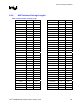
strobe signals. All length matching should be done from GMCH die to the ICH4-M die. Refer to the
package length Table 79 and Table 80.
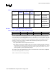
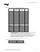
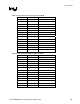
Table 78. Hub Interface Signals Internal Layer Routing Summary
Signal Min
length
(inch)
Max
length
(inch)
Width
(mils)
Space
(mils)
Misma
tch
length
(mils)
Relative
To
Space
with other
signals
(mils)
Notes
HL[10:0] 1.5” 6” 4 8 ± 100 Differential
HLSTB
pair
20
HLSTB
HLSTB#
1.5” 6” 4 8 ± 100 Data lines 20 HLSTB and
HLSTB# must
be ± 10 mils of
each other