
Design Guide

Hub Interface
R
190 Intel
®
855GM/855GME Chipset Platform Design Guide
10.2.2. Terminating HL[11]
The HL[11] signal exists on the ICH4-M but not the GMCH and is not used on the platform. HL[11]
must be pulled down to ground via a 56-Ω resistor.
10.3. Hub VREF/VSWING Generation/Distribution
The hub interface reference voltage (VREF) is used on both the GMCH (HLVREF) and the ICH4-M
(HIREF). The hub interface also has a reference voltage (VSWING) for the GMCH (PSWING) and the
ICH4-M (HI_VSWING), to control voltage swing and impedance strength of the hub interface buffers.
The VREF voltage requirements must be set appropriately for proper operation. See Table 81 for the
VREF and VSWING voltage specifications. Sections 10.3.1 to 10.3.4 provide details on the different
options for VREF and VSWING voltage divider circuitry requirements.
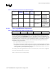
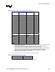
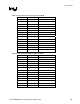
Table 81. Hub Interface VREF/VSWING Reference Voltage Specifications
VREF VSWING
HIREF (ICH4-M)
HLVREF (GMCH)
HI_VSWING (ICH4-M)
PSWING (GMCH)
NOTES
350 mV +/- 8%
800 mV +/- 8% See Sections 10.3.1, 10.3.2, 10.3.3, and 10.3.4 for
recommendations for the VREF/VSWING voltage generation
circuitry.
See Table 82, Table 83, and Table 84 for recommended
resistor values.
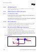
10.3.1. Single Generation Voltage Reference Divider Circuit
The GMCH and ICH4-M may share the same single voltage divider circuit. This option provides one
voltage divider circuit to generate both VREF and VSWING reference voltage. The reference voltage
for both VREF and VSWING must meet the voltage specification in Table 81. If the voltage
specifications are not met then individual locally generated voltage divider circuit is required. The
maximum trace length from the GMCH to ICH4-M is 4 inches or less. The voltage divider circuit should
be place midway between the GMCH and ICH4-M. Normal care needs to be taken to minimize
crosstalk to other signals (< 10-15 mV). If the trace length exceeds 4 inches then the locally generated
voltage reference divider should be used. See section 10.3.2 for the more details.