
Design Guide

I/O Subsystem
R
Intel
®
855GM/855GME Chipset Platform Design Guide 197
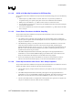
11.1.3. Secondary IDE Connector Requirements
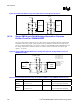
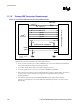
Figure 93. Connection Requirements for Secondary IDE Connector
Intel
®
ICH4-M
Secondary IDE Connector
PCIRST#
†
SDD[15:0]
SDA[2:0]
SDCS[3,1]#
SDIOR#
SDDREQ
SDDACK#
SDIOW#
SIORDY (SRDSTB / SWDMARDY# )
4.7K
8.2~10K
3.3V
3.3V
PDIAG# / CBLID#
IRQ[15]
GPIOy
CSEL
10K
22 - 47
Ω
†
Due to ringing,
PCIRST# must be
buffered
Follow these requirements for Secondary IDE Connector:
• 22 Ω - 47 Ω series resistors are required on RESET#. The correct value should be determined for
each unique motherboard design, based on signal quality.
• An 8.2 kΩ - 10 kΩ pull-up resistor is required on IRQ15 to VCC3_3.
• A 4.7-kΩ, pull-up resistor to VCC3_3 is required on PIORDY and SIORDY.
• Series resistors can be placed on the control and data lines to improve signal quality. The resistors
are placed as close to the connector as possible. Values are determined for each unique
motherboard design.
• The 10-kΩ resistor to ground on the PDIAG#/CBLID# signal is required on the Secondary
Connector. This change is to prevent the GPI pin from floating if a device is not present on the IDE
interface.