
Design Guide


I/O Subsystem
R
208 Intel
®
855GM/855GME Chipset Platform Design Guide
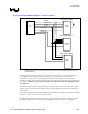
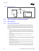
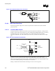
Figure 101. USBRBIAS Connection
Intel
®
ICH4-M
USBRBIAS
USBRBIAS#
22.6Ω+/- 1%
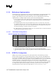
Table 89. USBRBIAS/USBRBIAS# Routing Summary
USBRBIAS/ USBRBIAS#
Routing Requirements
Maximum Trace Length Signal Length Matching Signal Referencing
5 on 5 500 mils N/A N/A
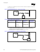
11.4.1.4. USB 2.0 Termination
A common-mode choke should be used to terminate the USB 2.0 bus. Place the common-mode choke as
close as possible to the connector pins. See Section 11.4.4 for details.
11.4.1.5. USB 2.0 Trace Length Pair Matching
USB 2.0 signal pair traces should be trace length matched. Max trace length mismatch between USB 2.0
signal pair should be no greater that 150 mils.
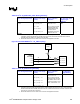
11.4.1.6. USB 2.0 Trace Length Guidelines
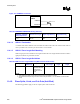
Table 90. USB 2.0 Trace Length Guidelines (With Common-mode Choke)
Configuration Signal
Referencing
Signal Matching Motherboard
Trace Length
Card Trace
Length
Maximum Total
Length
Back Panel Ground The max mismatch
between data pairs
should not be
greater than 150
mils
17 inches N/A 17 inches
NOTES:
1. These lengths are based upon simulation results and may be updated in the future.
2. All lengths are based upon using a common-mode choke (see Section 11.4.4.1 for details on common-mode
choke).
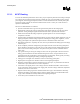
11.4.2. Plane Splits, Voids, and Cut-Outs (Anti-Etch)
The following guidelines apply to the use of plane splits voids and cutouts.