
Design Guide


I/O Subsystem
R
Intel
®
855GM/855GME Chipset Platform Design Guide 215
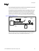
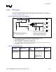
Added Considerations for Mixed Architecture
1. The bus switch must be powered by V
CC
_
SUSPEND.
2. Devices that are powered by the V
CC
_
SUSPEND
well must not drive into other devices that are
powered off. This is accomplished with the “bus switch”.
3. The bus bridge can be a device like the Phillips PCA9515.
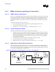
11.6.1.4. Calculating the Physical Segment Pull-Up Resistor
The following tables are provided as a reference for calculating the value of the pull-up resistor that may
be used for a physical bus segment. If any physical bus segment exceeds 400 pF, then a bus bridge
device like the Phillips PCA9515 must be used to separate the physical segment into two segments that
individually have a bus capacitance less than 400 pF.
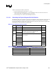
Table 91. Bus Capacitance Reference Chart
Device # of Devices/
Trace Length
Capacitance Includes Cap (pF)
ICH4-M 1 Pin Capacitance 12
CK408 1 Pin Capacitance 10
2 28 SO-
DIMMS
3
Pin Capacitance (10 pF) + 1 inch worth of trace
capacitance (2 pF/inch) per SO-DIMM and 2 pF
connector capacitance per SO-DIMM
42
2 86
3 129
4 172
5 215
PCI
Slots
6
Each PCI add-in card is allowed up to 40 pF + 3 pF per
each connector
258
≥24 48
≥36 72
Bus
Trace
Length
in inches
≥48
2 pF per inch of trace length
96
Table 92. Bus Capacitance/Pull-Up Resistor Relationship
Physical Bus Segment Capacitance Pull-Up Range (For Vcc = 3.3 V
0 to 100 pF 8.2 kΩ to 1.2 kΩ
100 to 200 pF 4.7 kΩ to 1.2 kΩ
200 to 300 pF 3.3 kΩ to 1.2 kΩ
300 to 400 pF 2.2 kΩ to 1.2 kΩ