
Design Guide


I/O Subsystem
R
Intel
®
855GM/855GME Chipset Platform Design Guide 219
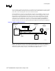
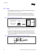
11.8.1. RTC Crystal
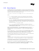
The Intel 82801DBM ICH4-M RTC module requires an external oscillating source of 32.768 kHz
connected on the RTCX1 and RTCX2 balls. Figure 109 documents the external circuitry that comprises
the oscillator of the ICH4-M RTC.
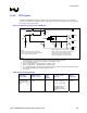
Figure 109. External Circuitry for the ICH4-M RTC
32.768 kHz
Xtal
0.047uF
10MΩ
VCCRTC
RTCX2
RTCX1
VBIAS
Vbatt
1uF
1kΩ
3.3V Sus
18pF
18pF
10MΩ
C1 C2
C3
R1
R2
Notes
Reference Designators Arbitrarily Assigned
3.3V Sus is Active Whenever System Plugged In
Vbatt is Voltage Provided By Battery
VBIAS, VCCRTC, RTCX1, and RTCX2 are ICH4 pins
VBIAS is used to bias the ICH4 Internal Oscillator
VCCRTC powers the RTC well of the ICH4
RTCX1 is the Input to the Internal Oscillator
RTCX2 is the feedback for the external crystal
NOTES:
1. The exact capacitor value needs to be based on what the crystal maker recommends.
(Typical values for C1 and C2 are 18 pF, based on crystal load of 12.5 pF)
2. V
CCRTC
: Power for RTC Well
3. RTCX2: Crystal Input 2 – Connected to the 32.7 68 kHz crystal.
4. RTCX1: Crystal Input 1 – Connected to the 32.7 68 kHz crystal.
5. V
BIAS
: RTC BIAS Voltage – This ball is used to provide a reference voltage, and this DC voltage sets a current,
which is mirrored throughout the oscillator and buffer circuitry.
6. V
SS
: Ground
Table 93. RTC Routing Summary
RTC Routing
Requirements
Maximum Trace
Length To Crystal
Signal
Length
Matching
R1, R2, C1, and C2
tolerances
Signal
Referencing
5 mil trace width
(results in ~2 pF per
inch)
1 inch NA
R1 = R2 = 10 M
Ω ± 5%
C1 = C2 = (NPO class)
See Section 11.8.2 for
calculating a specific
capacitance value for C1
and C2
Ground