
Design Guide

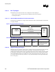

I/O Subsystem
R
Intel
®
855GM/855GME Chipset Platform Design Guide 221
Note that the temperature dependency of crystal frequency is a parabolic relationship (ppm / degree
square). The effect of changing the crystal’s frequency when operating at 0
°
C (25
°
C below room
temperature) is the same when operating at 50
°
C (25
°
C above room temperature).
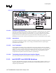
11.8.3. RTC Layout Considerations
Since the RTC circuit is very sensitive and requires high accuracy oscillation, reasonable care must be
taken during layout and routing of the RTC circuit. Some recommendations are:
1. Reduce trace capacitance by minimizing the RTC trace length. The ICH4-M requires a trace
length less than 1 inch on each branch (from crystal’s terminal to RTCXn ball). Routing the RTC
circuit should be kept simple to simplify the trace length measurement and increase accuracy on
calculating trace capacitances. Trace capacitance depends on the trace width and dielectric
constant of the board’s material. On FR-4, a 5-mil trace has approximately 2 pF per inch.
2. Trace signal coupling must be limited as much as possible by avoiding the routing of adjacent PCI
signals close to RTCX1 & RTCX2, and VBIAS.
3. Ground guard plane is highly recommended.
4. The oscillator V
CC
should be clean; use a filter, such as an RC low-pass, or a ferrite inductor.
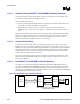
11.8.4. RTC External Battery Connections
The RTC requires an external battery connection to maintain its functionality and its RAM while the
ICH4-M is not powered by the system.
Example batteries are: Duracell* 2032, 2025, or 2016 (or equivalent), which can give many years of
operation. Batteries are rated by storage capacity. The battery life can be calculated by dividing the
capacity by the average current required. For example, if the battery storage capacity is 170 mAh
(assumed usable) and the average current required is 5 µA, the battery life will be at least:
170,000 µAh / 5 µA = 34,000 h = 3.9 years
The voltage of the battery can affect the RTC accuracy. In general, when the battery voltage decays, the
RTC accuracy also decreases. High accuracy can be obtained when the RTC voltage is in the range of
3.0 V to 3.3 V.
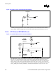
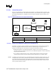
The battery must be connected to the ICH4-M via a Schottky diode circuit for isolation. The Schottky
diode circuit allows the ICH4-M RTC-well to be powered by the battery when the system power is not
available, but by the system power when it is available. To do this, the diodes are set to be reverse
biased when the system power is not available. Figure 110 is an example of a diode circuit that is used.