
Design Guide


I/O Subsystem
R
222 Intel
®
855GM/855GME Chipset Platform Design Guide
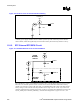
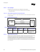
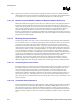
Figure 110. Diode Circuit to Connect RTC External Battery
V
CCSUS
3_3
VccRTC
1.0uF
1K
A standby power supply should be used in a mobile system to provide continuous power to the RTC
when available, which will significantly increase the RTC battery life and thereby the RTC accuracy.
11.8.5. RTC External RTCRST# Circuit
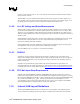
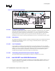
Figure 111. RTCRST# External Circuit for the ICH4-M RTC
V
CCSUS
3_3
VccRTC
1.0uF
1K
0.1uF
180K
RTCRST #
RTCRST#
CIRCUIT
DIODE/
BATTERY
CIRCUIT
The ICH4-M RTC requires some additional external circuitry. The RTCRST# signal is used to reset the
RTC well. The external capacitor and the external resistor between RTCRST# and the RTC battery
(VBAT) were selected to create an RC time delay, such that RTCRST# will go high some time after the
battery voltage is valid. The RC time delay should be in the range of 18 ms - 25 ms. Any resistor and
capacitor combination that yields the proper time constant is acceptable. When RTCRST# is asserted, bit
2 (RTC_PWR_STS) in the GEN_PMCON_3 (General PM Configuration 3) register is set to 1, and