
Design Guide


I/O Subsystem
R
Intel
®
855GM/855GME Chipset Platform Design Guide 229
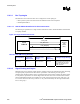
11.9.3.4. Critical Dimensions
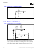
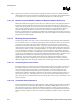
There are two dimensions to consider during layout. Distance ‘A’ from the line RJ-45 connector to the
magnetics module and distance ‘B’ from the Intel 82562ET or Intel 82562EM to the magnetics module.
The combined total distances A and B must not exceed 4 inches (preferably, less than 2 inches). (See
Figure 116.)
Figure 116. Critical Dimensions for Component Placement
Intel
®
82562ET/EM
B
A
EEPROM
Magnetics
Module
Line
RJ45
Intel
®
ICH4-M
Distance Priority Guideline
A 1 < 1 inch
B 2 < 1 inch
11.9.3.4.1. Distance from Magnetics Module to RJ-45 (Distance A)
The distance A in Figure 116 above should be given the highest priority in board layout. The distance
between the magnetics module and the RJ-45 connector should be kept to less than one inch of
separation. The following trace characteristics are important and should be observed:
• Differential Impedance: The differential impedance should be 100 Ω. The single ended trace
impedance will be approximately 50 Ω; however, the differential impedance can also be affected by
the spacing between the traces.
• Trace Symmetry: Differential pairs (such as TDP and TDN) should be routed with consistent
separation and with exactly the same lengths and physical dimensions (for example, width).
Caution: Asymmetric and unequal length traces in the differential pairs contribute to common mode noise. This
can degrade the receive circuit’s performance and contribute to radiated emissions from the transmit
circuit. If the Intel 82562ET must be placed further than a couple of inches from the RJ-45 connector,
distance B can be sacrificed. Keeping the total distance between the Intel 82562ET and RJ-45 will as
short as possible should be a priority.