
Design Guide


I/O Subsystem
R
Intel
®
855GM/855GME Chipset Platform Design Guide 231
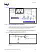
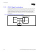
Figure 117. Termination Plane
N/C
RJ-45
Magnetics Module
RDP
RDN
TDP
TDN
Termination Plane
A
ddition Capacitance that may need to be
added for EFT testing
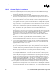
11.9.4. Intel 82562ET/EM Disable Guidelines
To disable the Intel 82562ET/EM, the device must be isolated (disabled) prior to reset (RSM_PWROK)
asserting. Using a GPIO, such as GPO28 to be LAN_Enable (enabled high), LAN will default to
enabled on initial power-up and after an AC power loss. This circuit shown below will allow this
behavior. The BIOS controlling the GPIO can disable the LAN micro-controller.
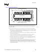
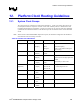
Note: LAN_RST# needs to be held low for 10ms after power is stable. It is assumed that RSMRST# logic will
provide this delay. Because GPIO28 will default to high during power up, an AND gate has been
implemented to ensure the required delay for LAN_RST# is met.
Figure 118. Intel 82562ET/EM Disable and Power Down Circuitry
Intel® 82562EM/ET Disable
3.3V Sus
10K 5%
10K 5%
LAN_RST#
GPIO_LAN_ENABLE MMBT3906
There are four pins which are used to put the Intel 82562ET/EM controller in different operating states:
Test_En, Isol_Tck, Isol_Ti, and Isol_Tex. The table below describes the operational/disable features for
this design.