
Design Guide
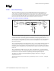

Platform Clock Routing Guidelines
R
Intel
®
855GM/855GME Chipset Platform Design Guide 243
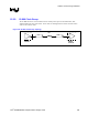
3. To minimize skew it is recommended that all clock pairs be length matched from CK408 pin to CPU and GMCH
die-pad, and length compensated on the motherboard for differences in package length and for
socket/interposer effective length. A table of package lengths and equivalent socket lengths are provided.
4. The motherboard length of the ITP connector clock pair should be matched to the sum of the motherboard
length of the CPU clock pair and the BPM[3:0]# signals.
5. A trace length offset (depends on CK408 vendor clock skew) between CLK66 going to the GMCH (GCLKIN)
and HCLK going to the GMCH (BCLK) is recommended in order to prevent the CLK66 rising edge from
occurring within the +/- 350ps keepout area on either side of the HCLK edge. See Section 12.2.1.3 for details.
12.2.1.1. Host Clock Group General Routing Guidelines
When routing the 100-MHz differential clocks, do not split up the two halves of a differential clock pair
between layers, and route to all agents on the same physical routing layer referenced to ground.
If a layer transition is required, make sure that the skew induced by the vias used to transition between
routing layers is compensated in the traces to other agents.
Do not place vias between adjacent complementary clock traces. Vias placed in one half of a differential
pair must be matched by a via in the other half. Differential vias can be placed within length L1,
between clock driver and Rs, if needed to shorten length L1.
12.2.1.2. Clock to Clock Length Matching and Compensation
The HCLK pairs to the CPU and GMCH should be matched as close as possible in total length from
CK408 pin to the die-pad of the receiving device. In addition, the L1/L1’ segments of all three clock
pairs should be length matched to within ± 10 mils. Pair to pair overall length matching requires
knowledge of the package lengths of various CPUs, and the GMCH, as well as the effective length of
the CPU socket/interposer if used. This information is provided in Table 100.
Once routing lengths are defined for the CPU and GMCH, match the motherboard length of the ITP
clock pair to the motherboard length of the CPU clock pair.
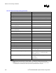
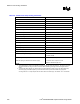
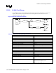
Table 100. Clock Package Length
Parameter Length
Intel Pentium M Processor / Intel Celeron M Processor
Package Length
485 mils
Intel 855GM/GME Chipset GMCH Package Length 1142 mils
CPU Socket Equivalent Length 157 mils
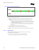
12.2.1.3. Host Clock to CLK66 Routing Recommendations
The rising edge of the HCLK (BCLK) input must either lead or lag the rising edge of CLK66
(GCLKIN) by more than 350 ps at the input balls of the GMCH as measured at the 50% point of each
rising edge. Refer to Figure 124 for details.