
Design Guide

Intel 855GM/GME Chipset Based System Power Delivery Guidelines
R
262 Intel
®
855GM/855GME Chipset Platform Design Guide
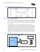
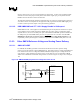
Figure 135. Example V
5REF
/ V
5REFSUS
Sequencing Circuitry
13.4.3.3. V
5REFSUS
Design Guidelines
The aforementioned rule for V
5REF
also applies to the V
5REF
_
SUS
input pin. However, in some platforms,
the V
CCSUS3
_
3
rail is derived from the V
CCSUS5
and therefore, the V
CCSUS3
_
3
rail will always come up after
the V
CCSUS5
rail. As a result, V
5REF
_
SUS
will always be powered up before V
CCSUS3
_
3
. In platforms where
the V
CCSUS3
_
3
rail is not derived from the V
CCSUS5
rail, the V
5REF
sequencing rule must be comprehended
in the platform design.
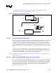
In order to meet reliability and testing requirements for the USB interface, the following design
recommendations for the V
5REF_SUS
pins of the ICH4-M should be followed. There are changes to the
USB specification regarding continuous short conditions must be addressed. The USB 1.1 specification
requires host controllers to withstand a continuous short between the USB 5-V connector supply and a
USB signal at the connector. However, the duration is unspecified. The USB 2.0 specification requires
this duration to be at least 24 hours. This in turn requires that the V
5REFSUS
pin be at 5 V as long as the
attached USB devices are powered. The recommendation is to provide a +V5ALWAYS (active S0-S5)
supply to the V
5REFSUS
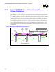
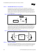
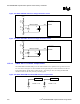
pin if available as shown in Figure 136. However, if support for wake on USB
from S3 and support for self-powered USB devices are not required, then option shown in Figure 137
can be used. V
5REFSUS
can be supplied by combination of +V5S (active in S0 only) and +V3ALWAYS
(active S0-S5).
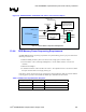
Figure 136. V5REFSUS With +V5ALWAYS Connection Option
+V5ALWAYS
USB D+
V5REF_SUS1
V5REF_SUS2
USB D-
ICH4 - M
USB Power (5V)
GND
Customer specific or
Intel recommended
USB interface
circuits
Customer specific or
Intel recommended
USB power circuit
0.1uF
USB D+
V5REF_SUS1
USB D-
ICH4 - M
USB Power (5V)
GND
Customer specific or
Intel recommended
USB interface
circuits
Customer specific or
Intel recommended
USB power circuit
0.1uF