
Design Guide

Intel 855GM/GME Chipset Based System Power Delivery Guidelines
R
Intel
®
855GM/855GME Chipset Platform Design Guide 273
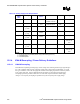
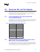
Table 115. ICH4-M Decoupling Requirements
Pin Name Configuration F Qty
VCC3_3 Connect to Vcc3_3S 0.1 µF 6
VCCSUS3_3 Connect to Vcc3_3A 0.1 µF 2
VCCLAN3_3 Connect to Vcc3_3 0.1 µF 2
V_CPU_IO Connect to Vccp IMVP-IV 1 µF
1 µF
1
1
VCC1_5 Connect to Vcc1_5S 0.1 µF 2
VCCSUS1_5 Connect to Vcc1_5A 0.1 µF 2
VCCLAN1_5 Connect to Vcc1_5 0.1 µF 2
V5REF Connect to Vcc5_Ref 0.1 µF 1
V5REF_SUS Connect to Vcc5A 0.1 µF 1
VCCRTC Connect to Vcc_RTC 0.1 µF 1
VCCHI Connect to Vcc1_5S 0.1 µF 2
0.1 µF 1
VCCPLL Connect to Vcc1_5S
0.01 µF 1
NOTE: Capacitors should be placed less than 100 mils from the package.
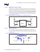
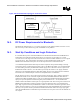
13.5.5. Hub Interface Decoupling
To improve I/O power delivery, use two 0.1-µF capacitors per each component (i.e. the ICH4-M and
GMCH). These capacitors should be placed within 50 mils from each package, adjacent to the rows that
contain the hub interface. If the layout allows, wide metal fingers running on the V
SS
side of the board
should connect the V
CC
HI side of the capacitors to the V
CC
HI power pins. Similarly, if layout allows,
metal fingers running on the V
CC
HI side of the board should connect the groundside of the capacitors to
the V
SS
power pins.
13.5.6. FWH Decoupling
Place a 0.1-µF capacitor between the V
CC
supply pins and the V
SS
ground pins to decouple high
frequency noise, which may affect the programmability of the device. Additionally, place a 4.7-µF
capacitor between the V
CC
supply pins and the V
SS
ground pins to decouple low frequency noise. The
capacitors should be placed no further than 390 mils from the V
CC
supply pins.
13.5.7. General LAN Decoupling
The following are general LAN decoupling recommendations:
• All VCC pins should be connected to the same power supply.
• All VSS pins should be connected to the same ground plane.
• Four to six decoupling capacitors, including two 4.7-µF capacitors are recommended
• Place decoupling as close as possible to power pins.