
Design Guide

Intel Pro/Wireless 2100/2100A – Bluetooth Coexistence Interface Design Requirements
R
Intel
®
855GM/855GME Chipset Platform Design Guide 275
14. Intel Pro/Wireless 2100/2100A –
Bluetooth Coexistence Interface
Design Requirements
This section describes the design requirements needed to support the Intel PRO/Wireless 2100/2100A
wireless component, a critical component of the latest Intel Centrino mobile technology. The following
discussion provides guidelines on the interface design between the Intel PRO/Wireless 2100/2100A
802.11a/b wireless LAN device and the Bluetooth module of choice supporting the coexistence
algorithm. The following areas will be covered:
1. Coexistence interface design requirements
2. DC power requirements for Bluetooth
3. Start up conditions and logic protection
Detailed information on the coexistence specification is disclosed in the RS - Banias Coexistence System
Specification and Intel Banias Wireless Platform Design Guide.
14.1. PCB Interface Requirements
The Intel PRO/Wireless 2100/2100A (2100/2100A) wireless LAN device is a PCI based component that
is designed to fit into the standard mini-PCI connector. No standard connector is specified for use with
the Bluetooth* module and vendor implementations may vary. The coexistence solution that exists
between the Intel PRO/Wireless 2100/2100A and Bluetooth* modules is composed of a two signal
interface. These two signals are used to transmit the channel number and clock signals between the two
devices.
Although these traces do not have any length, width or impedance matching constraints, a typical
routing solution of 5 mils trace width on 5 mils spacing is recommended. The 2100/2100A’s PCI pin
#43 needs to be routed to the Channel_Data signal of the Bluetooth module. The 2100/2100A’s PCI pin
#36 needs to be routed to the Channel_Clock signal of the Bluetooth module.
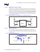
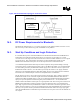
In order to protect the Bluetooth module and 2100/2100A modules, CMOS tri-state buffers (e.g.
74AHC1G126 or equivalent) and a 1-kΩ resistor are recommended as illustrated in Figure 148. A
detailed explanation of this recommendation is described in Section14.3.