
Design Guide

Platform Design Checklist
R
284 Intel
®
855GM/855GME Chipset Platform Design Guide
16.4. Intel Pentium M Processor / Intel Celeron M Processor
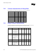
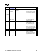
16.4.1. Resistor Recommendations
Pin Name System
Pull-up/Pull-down
Series
Termination
Voltage
Translation
Notes
9
A20M# Point-to-point connection to ICH4-M.
BR0# Point-to-point connection to GMCH.
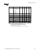
COMP0,
COMP2
27.4
Ω ± 1% pull-
down to gnd
Resistor placed within 0.5” of processor
pin. Trace should be 27.4
Ω ± 15%.
COMP1,
COMP3
54.9
Ω ± 1% pull-
down to gnd
Resistor placed within 0.5” of processor
pin. Trace should be 55
Ω ± 15%.
DPSLP# Connect to GMCH and ICH4-M.
FERR#
56
Ω pull-up to VCCP 56 Ω from pull-
up to ICH4-M
pin.
Point-to-point connection to ICH4-M,
with pull-up resistor and series resistor
placed by ICH4-M.
GTLREF
1 K
Ω ± 1% pull-up to
VCCP
2 K
Ω ± 1% pull-down
to gnd
Voltage divider should be placed within
0.5” of processor pin.
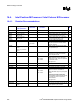
IERR#
56
Ω pull-up to VCCP
IERR# is a 1.05 V signal. Voltage
translation logic and/or series resistor
may be required if used.
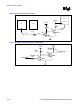
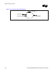
INIT#
R1 = 1.3 K
Ω
R2 = 330
Ω
Rs = 330
Ω
Point-to-point connection to ICH4-M.
Voltage transition circuit is required if
connecting to FWH. Signal is T-split from
the ICH4-M to FWH.
See Figure 149.
IGNNE# Point-to-point connection to ICH4-M.
LINT0/INTR Point-to-point connection to ICH4-M.
LINT1/NMI Point-to-point connection to ICH4-M.
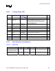
PROCHOT#
56
Ω pull up to VCCP
R1 = 1.3 KΩ
R2 = 330
Ω
Rs = 330
Ω
PROCHOT# is a VCCP signal. This
signal is not used on the CRB. So,
voltage translation logic may be required
if used.
If Voltage Translation is Required:
Driver isolation resistor should be placed
at the beginning of the T-split to the
system receiver.
See Figure 150.
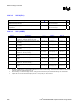
PSI# Can be left as NC, if not used for IMVP.
PWRGOOD
330
Ω pull-up to
VCCP
Point-to-point connection to ICH4-M, with
resistor placed by the processor.