
Design Guide
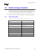

Platform Design Checklist
R
Intel
®
855GM/855GME Chipset Platform Design Guide 287
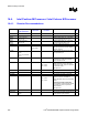
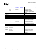
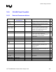
16.4.2. In Target Probe (ITP)
Pin Name System
Pull-up /Pull-down
Series
Termination
Resistor (
Ω)
Notes
9
BPM[5:0]# Connect to processor directly.
DBR#
150-240
Ω pull-up to
V3ALWAYS
If using ITP on interporser card, then DBR# should also be
connected to DBRESET pin at the processor. The 150-240
Ω pull-up resistor should be placed within 1 ns of the
ITP700FLEX connector. The CPU should not be power
cycled when DBR# is asserted.
RESET#
54.9
Ω ± 1% pull-up to
VCCP
IF USING ITP700FLEX
22.6 Ω ± 1%
from pull-up to
ITP700FLEX
See notes in Section 16.4.1
FBO Connect to TCK pin of processor.
TCK
27.4
Ω ± 1% pull-down
to gnd
Connect to processor, with resistor placed by ITP.
TDI
150
Ω pull-up to VCCP
Connect to processor, with resistor placed by the processor.
TDO
54.9
Ω ± 1% pull-up to
VCCP
22.6 Ω ± 1%
from pull-up to
ITP700FLEX
Connect to processor, with resistors placed by ITP. If ITP
not used, this signal can be left as NC.
TMS
39.2
Ω ± 1% pull-up to
VCCP
Connect to processor, with resistor placed by ITP.
TRST#
680
Ω pull-down to gnd
Connect to processor.
VTAP,
VTT[1:0]
Connect to VCCP One 0.1 µF decoupling cap is required.
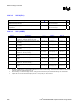
16.4.3. Decoupling Recommendations
16.4.3.1. VCCP (I/O)
Description C, µF ESR, mΩ ESL, nH Notes
9
Low Frequency Decoupling
(Polymer Covered Tantalum -
POSCAP, Neocap, KO Cap)
1 x 150 µF 42 mΩ (typ) / 2 2.5 nH / 12
High Frequency Decoupling
(0603 MLCC, >= X7R)
10 x 0.1 µF 16 mΩ (typ) / 10 0.6 nH / 10