
Design Guide

Platform Design Checklist
R
288 Intel
®
855GM/855GME Chipset Platform Design Guide
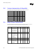
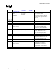
16.4.3.2. VCCA (PLL)
Description C, µF Notes
9
Mid Frequency Decoupling (Polymer Covered Tantalum -
POSCAP, Neocap, KO Cap)
4 x 10 µF Place one 10 µF and one 0.01 µF
for each VCCA pin.
High Frequency Decoupling (0603 MLCC, >= X7R) Place next to
the processor
4 x 0.01 µF Place one 10 µF and one 0.01 µF
for each VCCA pin.
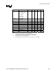
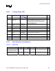
16.4.3.3. VCC (CORE)
Option Description C, µF ESR, mΩ ESL, nH
9
#1 Low-Frequency Decoupling (Polymer Covered
Tantalum – POSCAP, Neocap, KO Cap)
12 x 150 µF 36 mΩ (typ) / 12 2.5 nH / 12
Mid-Frequency Decoupling (0612 MLCC, X5R
or better)
15 x 2.2 µF 5 mΩ (typ) / 15 0.2 nH / 15
#2 Low-Frequency Decoupling (1206 MLCC, X5R
or better)
40x10 µF 5 mΩ (typ) / 40 1.2 nH / 40
Mid-Frequency Decoupling (0612 MLCC, X5R
or better)
15 x 2.2 µF 5 mΩ (typ) / 15 0.2 nH / 15
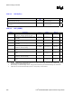
#3
Low Frequency Decoupling (Polymer Covered
Aluminum – SP Cap, A0 Cap)
5 x 330 µF 15 m
Ω (max) / 5 3.5 nH / 5
Low Frequency Decoupling (1206 MLCC, >=
X5R)
25 x 10 µF 5 m
Ω (typ) / 25 1.2 nH / 25
Mid Frequency Decoupling (0612 MLCC, >=
X5R)
15 x 2.2 µF 5 m
Ω (typ) / 15 0.2 nH / 15
#4
Low-Frequency Decoupling (Polymer Covered
Aluminum – SP CAP, AO Cap)
4 x 220 µF 12 mΩ (max) / 4 3.5 nH / 4
Mid-Frequency Decoupling (0805 MLCC>=
X5R)
35 x 10
µF 5 mΩ (typ) / 35 0.6 nH / 35
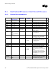
NOTES:
1. Decoupling guidelines are recommendations based on our reference board design. The Intel Customer Reference Board uses
option #4. This is the preferable option to use.
2. When deciding on overall decoupling solution, customers will need to take layout & PCB board design into consideration.
3. Options #4 is to be used with small footprint (100 mm
2
or less) 0.36 µH ± 20% inductors.