
Design Guide

Platform Design Checklist
R
296 Intel
®
855GM/855GME Chipset Platform Design Guide
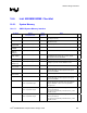
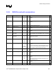
16.6.4.2. DVO
Pin Name System
Pull-up/Pull-down
Notes
9
DVORCOMP
40.2
Ω 1% pull-down to gnd
Trace should be 10-mil wide with 20-mil spacing.
GVREF
1 k
Ω 1% pull-up to Vcc1_5
1 k
Ω 1% pull-down to gnd
Signal voltage level = 1/2 of Vcc1_5. Need 0.1 µF cap at pin.
DVOCD[11:0]
DVOCCLK
DVOCCLK#
DVOCHSYNC
DVOCVSYNC
DVOCBLANK#
If unused, these signals can be left as NC.
DVOCFLDSTL
100 k
Ω pull-down to gnd
Pull-down resistor required only if signal is unused (10 k-100
k). It is up to DVO device to drive this signal.
DVOBCINTR#
100 k
Ω pull-up to Vcc1_5
Pull-up resistor required only if signal is unused (10 k-100 k).
It is up to the DVO device to drive this signal.
DVOBCCLKINT
100 k
Ω pull-down to gnd
Pull-down resistor required only if signal is unused (10 k-100
k). It is up to the DVO device to drive this signal.
DVOBD[11:0]
DVOBCLK
DVOBCLK#
DVOBHSYNC
DVOBVSYNC
DVOBBLANK#
If unused, these signals can be left as NC.
DVOBFLDSTL
(pin M2)
100 k
Ω pull-down to gnd
Pull-down resistor required only if this signal is unused (10 k-
100 k).
MI2CCLK,
MI2CDATA
2.2 k
Ω pull-up to Vcc1_5
Pull-up resistor required on each signal even if they are
unused (2.2 k-100 k). This signal is 1.5-V tolerant. It may
require voltage translation circuit.
MDVICLK,
MDVIDATA
2.2 k
Ω pull-up to Vcc1_5
Pull-up resistor required on each signal even if they are
unused (2.2 k-100 k). This signal is 1.5-V tolerant. It may
require voltage translation circuit.
MDDCCLK,
MDDCDATA
2.2 k
Ω pull-up to Vcc1_5
Pull-up resistor required on each signal even if they are
unused (2.2 k-100 k). This signal is 1.5V tolerant. It may
require voltage translation circuit.
ADDID[6:0] Leave as NC.
ADDID7
1 k
Ω pull-down to gnd if DVO
device is onboard
If DVO interface is not used, this signal can be left as “no
connect”. Otherwise, pull-down is needed.
DVODETECT
1 k
Ω pull-up to Vcc1_5
if DVO interface is unused
If DVO interface is used, leave as NC. This signal has
internal pull-down.
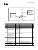
DPMS Connect to 1.5-V version of ICH4-M’s SUSCLK or a clock
that runs during S1.
See Figure 154.