
Design Guide

Platform Design Checklist
R
312 Intel
®
855GM/855GME Chipset Platform Design Guide
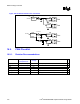
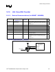
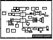
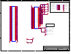
Figure 158. Good Downstream Power Connection
Port
Port
GGnndd
VVcccc
44
1
1
470pF
Thermiste
r
220uF
GGnndd
VVcc cc
44
1
1
470pF
5V
5V
Switch5V Sus
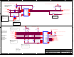
Port
Port
GGnndd
VVcccc
44
1
1
470pF
Ferrite Bead
100-150uF
GGnndd
VVcc cc
44
1
1
470pF
PWR
Distribution
Switch
5V Sus
Ferrite Bead
100-150uF
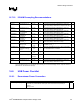
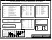
16.9. FWH Checklist
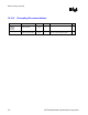
16.9.1. Resistor Recommendations
Pin Name System
Pull-up/Pull-down
Series
Damping
Notes
9
FGPI[4:0]
100
Ω pull-down to gnd
Each signal requires a 100 Ω pull-down resistor.
IC
10 k
Ω pull-down to gnd
RST#
100
Ω
ID[3:0]
Signals are recommended to be connected to test points.
RSVD[5:1]
Signals are recommended to be connected to test points.
NC[8:1] The signals should be left as NC (“Not Connected”)