
Design Guide

Platform Design Checklist
R
Intel
®
855GM/855GME Chipset Platform Design Guide 313
16.10. LAN / HomePNA Checklist
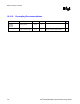
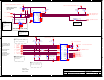
16.10.1. Resistor Recommendations (for 82562ET / 82562EM)
Pin Name System
Pull-up/Pull-down
Term
Resistor
Notes
9
ISOL_EX,
ISOL_TCK,
ISOL_TI
10 k
Ω pull-up to
VccSus3_3LAN
If LAN is enabled, all three signals needs to be pulled
up to VccSus3_3LAN through a common 10 k
Ω pull-up
resistor.
See Figure 159.
RBIAS10
549
Ω ± 1%pull-down to gnd
RBIAS100
619
Ω ± 1%pull-down to gnd
RDP, RDN
121
Ω ±1%
Connect 121-ohm resistor between RDP and RDN.
TDP, TDN
100
Ω ± 1%
Connect 100-ohm resistor between TDP and TDN.
TESTEN
100
Ω pull-down to gnd
X1, X2 Connect a 25-MHz crystal across these two pins. 22pF
on each pin to ground.
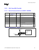
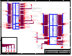
LAN_RST# On CRB, the power monitoring logic waits for
PM_PWROK to go high before deasserting this signal
to enable the LAN device. It also keeps this signal high
during S3.
See Figure 159.
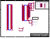
Figure 159. LAN_RST# Design Recommendation
ISOL_TCK
ISOL_TI
ISOL_EX
VccSus3_3LAN
LAN_RST#
10k
82562EM