
Design Guide

Intel Pentium M/Celeron M Front Side Bus Design Guidelines
R
46 Intel
®
855GM/855GME Chipset Platform Design Guide
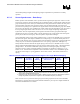
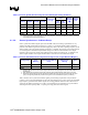
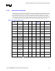
Table 7. Processor PSB Source Synchronous Address Signal Routing Guidelines
Signal Names Transmission Line Type Total Trace Length
Nominal
Impedance (
Ω)
Width &
Spacing (mils)
Address
Group #1
Address
Group #2
Min
(inches)
Max
(inches)
A[16:3]# A[31:17]# Strip-line 0.50 6.5 55 ± 15% 4 & 8
REQ[4:0]# Strip-line 0.50 6.5 55 ± 15% 4 & 8
ADSTB#[0] ADSTB#[1] Strip-line 0.50 6.5 55 ± 15% 4 & 12
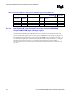
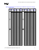
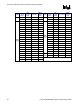
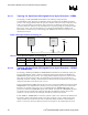
4.1.3.5. Intel Pentium M / Intel Celeron M Processor and Intel 855GM/GME
Chipset GMCH PSB Signal Package Lengths
Table 8 lists the preliminary package trace lengths of the Intel Pentium M / Intel Celeron M processor
and the Intel 855GM/GME chipset GMCH for the source synchronous data and address signals. The
processor PSB package signals within the same group are routed to the same package trace length, but
the GMCH package signals within the same group are not routed to the same package trace length. As
a result of this package length compensation is required for GMCH. Refer to Section 4.1.3.1 for length
matching constrains and to Section 4.1.3.2 package length compensation for further details. The
processor package traces are routed as micro-strip lines with a nominal characteristic impedance of 55
Ω ± 15%.