
Design Guide

Intel Pentium M/Celeron M Front Side Bus Design Guidelines
R
Intel
®
855GM/855GME Chipset Platform Design Guide 67
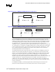
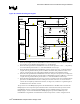
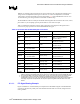
Figure 29. ITP700FLEX Debug Port Signals
L8
L6
L7
L3
L2
L4
L1
L5
PREQ#
BPM[3:0]# BPM[5:0]#
BPM[3: 0] #
BPM[ 4] #
PRD Y#
VCC
DBR#
RESET#
RESET#
RESET #
CPURESET#
ITPCLK[1:0]
BCLK[ 1: 0]
Bani asC LK[ 1: 0 ]
GMCHCLK[1:0]
BCLK[ 1: 0]
BCLKp
CK408
Processor
GMCH
220
Ω
5%
1.0 5 v
22. 6
Ω
1%
BPM[ 5] #
RESET I TP #
240
Ω
5%
BCLKn
1.05v
VTT
0.1uF
VTT
150
Ω
5%
TDI
1.05v
TDI TDI
TDI
39. 2
Ω
1%
TMS
1.0 5 v
TMS TMS
TMS
680
Ω
5%
TRST#
TRST# TRST#
TRST#
27. 4
Ω
1%
TCK
TCKTCK
TCK
54. 9
Ω
1%
TDOITP
1.0 5 v
TDO TDO
22. 6
Ω
1%
TDO
FBO
FBO
FBO
VTAP
240
Ω
5%
VCC
DBA#
DBR#
DBA#
To connect to the debug port, follow the steps below:
1. Route the TDI signal between the ITP700FLEX connector and the processor. A 150-Ω ± 5% pull-
up to VCCP (1.05 V) should be placed within ± 1.5” of the TDI pin.
2. Route the TMS signal between ITP700FLEX connector and the processor. A 39.2-± 1% pull-up
to VCCP should be placed within ± 1” of the ITP700FLEX connector pin.
3. Route the TRST# signal between ITP700FLEX connector and the processor. A 510-Ω to 680-Ω ±
5% pull-down to ground should be placed on TRST#. Placement of the pull down resistor is not
critical. Avoid having any trace stub from the TRST# signal line to the termination resistor.
4. Route the TCK signal from the ITP700FLEX connector’s TCK pin to the processor’s TCK pin and
then fork back from the TCK pin and route back to ITP700FLEX connector’s FBO pin. A 27.4-Ω ±
1% pull-down to ground should be placed within ± 1” of the ITP700FLEX connector pin.
5. Route the TDO signal from the processor to a 54.9-Ω ± 1% pull-up resistor to VCCP that should be
placed close to ITP700FLEX connector’s TDO pin. Then insert a 22.6-Ω ± 1% series resistor to
connect the 54.9-Ω pull-up and the ITP connector (see Figure 29). Limit the L1 segment length of
the TDOITP net to be less than 1.0 inch.
The processor drives the BPM[4:0]# signals to the ITP700FLEX at a 100-MHz clock rate. Route the
BPM[4:0]# as a Zo=55 Ω point-to-point transmission line connection between the processor and the
ITP700FLEX connector. Connect the ITP700FLEX connector’s BPM[3:0]# pins to processor’s
BPM[3:0]# pins. Connect the ITP700FLEX’s BPM[4]# signal to processor’s PRDY# pin. The
ITP700FLEX’s integrated far-end terminations as well as the processor’s AGTL+ integrated on-die