
Design Guide

System Memory Design Guidelines (DDR-SDRAM) for SO-DIMM configuration
R
86 Intel
®
855GM/855GME Chipset Platform Design Guide
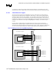
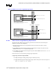
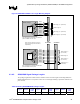
36 for the definition of the various trace segments. The length tuning requirements are also depicted in
Figure 37. Refer to Section 6.1 for more details on length matching and length formula requirements.
Length range formula for SO-DIMM0:
X
0
= SCK/SCK#[2:0] total reference length, including package length
Y
0
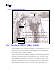
= SDQS[8:0] total length = GMCH package + L1 + L2 + S0, as shown in Figure 37,
where: ( X
0
– 1.0” ) ≤ Y
0
≤ ( X
0
+ 0.5” ) for DDR 200/266
( X
0
– 2.0” ) ≤ Y
0
≤ ( X
0
+ 0.5” ) for DDR 200/266/333
Length range formula for SO-DIMM1,
X
1
= SCK/SCK#[5:3] total reference length, including package length
Y
1
= SDQS[8:0] total length = GMCH package + L1 + L2 + L3 + S1, as shown Figure 37,
where: ( X
1
– 1.0” ) ≤ Y
1
≤ ( X
1
+ 0.5” ) for DDR 200/266
( X
0
– 2.0” ) ≤ Y
0
≤ ( X
0
+ 0.5” ) for DDR 200/266/333
Length matching is only performed from the GMCH to the SO-DIMMs, and does not involve the length
of L4, which can vary over its entire range. Intel recommends that routing segment length L3 between
SO-DIMM0 to SO-DIMM1 be held fairly constant and equal to the offset between clock reference
lengths X0 and X1. This will produce the most straightforward length-matching scenario. Note that a
nominal SDQS package length of 750 mils can be used to estimate MB lengths prior to performing
package length compensation. Refer to Section 6.2 for more details on package length compensation.