
Document


Datasheet 29
Package Mechanical Specifications and Pin Information
4 Package Mechanical
Specifications and Pin
Information
4.1 Package Mechanical Specifications
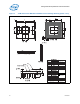
The processor is available in 4-MB and 2-MB, 478-pin Micro-FCPGA packages. The
package mechanical dimensions, keep-out zones, processor mass specifications, and
package loading specifications are shown in Figure 3 through Figure 6.
The mechanical package pressure specifications are in a direction normal to the surface
of the processor. This requirement is to protect the processor die from fracture risk due
to uneven die pressure distribution under tilt, stack-up tolerances and other similar
conditions. These specifications assume that a mechanical attach is designed
specifically to load one type of processor.
Moreover, the processor package substrate should not be used as a mechanical
reference or load-bearing surface for the thermal or mechanical solution. Please refer
to the Santa Rosa Platform Mechanical Design Guide for more details.
Note: For E-step based processors refer the 4-MB and Fused 2-MB package drawings. For M-
step based processors refer to the 2-MB package drawings.