
Intel Celeron D Processor 3xx Sequence

Datasheet 67
Thermal Specifications and Design Considerations
5.2.5 T
CONTROL
and Fan Speed Reduction (Optional)
T
CONTROL
and Fan Speed Reduction are not requirements for the Celeron D processor on 90 nm
process and in the 478-pin package, but are provided as options for platforms that can use these
features. T
CONTROL
is part of the temperature specification that defines temperature for system fan
speed management. The BIOS reads the T
CONTROL
value once and configures the fan control chip
appropriately. The value for T
CONTROL
will be set during manufacturing and is unique for each
processor. The T
CONTROL
temperature for a given processor can be obtained by reading the
IA32_TEMPERATURE_TARGET MSR in the processor and is in hexadecimal format.
The value of T
CONTROL
(read from IA32_TEMPERATURE_TARGET MSR) can vary from 00 h
to 1E h (0 to 30 °C). The T
CONTROL
read from the IA32_TEMPERATURE_TARGET MSR needs
to be added to a base value of 50 °C to get the final value for comparison with Thermal Diode
temperature (T
DIODE
). T
CONTROL
plus the base value of 50 °C is compared to the temperature
reported by T
DIODE
. When the T
DIODE
temperature is below T
CONTROL
, fan speed can be at
minimum. As T
DIODE
approaches T
CONTROL
plus the base value of 50 °C, fan speed should be
increased in an effort to maintain T
DIODE
at/below T
CONTROL
plus the base value of 50 °C. For
platforms that support this feature, the processor T
C-MAX
specification must be within guidelines,
as defined by the processor thermal specifications in Table 5-1. For 845G/x chipset platforms that
were not designed to read IA32_TEMPERATURE_TARGET MSR, the processor must be kept
within the T
C-MAX
specification.
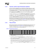
5.2.6 Thermal Diode
The processor incorporates an on-die thermal diode. A thermal sensor located on the system board
may monitor the die temperature of the processor for thermal management/long term die
temperature change purposes. Table 5-2 and Table 5-3 provide the diode parameter and interface
specifications. This thermal diode is separate from the Thermal Monitor’s thermal sensor and
cannot be used to predict the behavior of the Thermal Monitor.
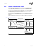
Table 5-2. Thermal Diode Parameters
Symbol Parameter Min Typ Max Unit Notes
I
FW
Forward Bias Current 11 — 187 uA
1
NOTES:
1. Intel does not support or recommend operation of the thermal diode under reverse bias.
n Diode Ideality Factor 1.0083 1.011 1.0137 —
2,3,4
2. Characterized at 75 °C.
3. Not 100% tested. Specified by design characterization.
4. The ideality factor, n, represents the deviation from ideal diode behavior as exemplified by the diode equation:
I
FW
= I
S
* (e
qV
D
/nkT
–1)
where I
S
= saturation current, q = electronic charge, V
D
= voltage across the diode, k = Boltzmann Constant,
and T = absolute temperature (Kelvin).
R
T
Series Resistance 3.242 3.33 3.594 Ω
2,3,5
5. The series resistance, R
T
, is provided to allow for a more accurate measurement of the junction temperature. R
T
, as defined,
includes the pins of the processor but does not include any socket resistance or board trace resistance between the socket
and the external remote diode thermal sensor. R
T
can be used by remote diode thermal sensors with automatic series re-
sistance cancellation to calibrate out this error term. Another application is that a temperature offset can be manually calcu-
lated and programmed into an offset register in the remote diode thermal sensors as exemplified by the equation:
T
error
= [R
T
* (N-1) * I
FWmin
] / [nk/q * ln N]
where T
error
= sensor temperature error, N = sensor current ratio, k = Boltzmann Constant, q = electronic
charge.