
Intel Celeron Processor for the PGA370 Socket up to 1.40 GHz on 0.13 Micron Process Datasheet

14 Datasheet
Intel
®
Celeron
®
Processor for PGA370 up to 1.40 GHz on 0.13 µ Process
2.2 Clock Control and Low Power States
Processors allow the use of Sleep, and Deep Sleep states to reduce power consumption by stopping
the clock to internal sections of the processor, depending on each particular state. See Figure 3 for a
visual representation of the processor low power states.
For the processor to fully realize the low current consumption of the Stop-Grant, Sleep and Deep
Sleep states, a Model Specific Register (MSR) bit must be set. For the MSR at 02AH (Hex), bit 26
must be set to a ‘1’ (this is the power on default setting) for the processor to stop all internal clocks
during these modes. For more information, see the Intel Architecture Software Developer’s
Manual, Volume 3: System Programming Guide.
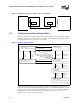
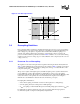
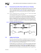
Figure 2. AGTL Bus Topology in a Uniprocessor Configuration
Processor Chipset
I/OI/O
Note: RESET# requires external termination.
Figure 3. Stop Clock State Machine
PCB757a
2. Auto HALT Power Down State
BCLK running.
Snoops and interrupts allowed.
HALT
I
ns
t
ruc
ti
on an
d
HALT Bus Cycle Generated
INIT#, BINIT#, INTR,
SMI#, RESET#
1. Normal State
Normal execution.
STPCLK#
Asserted
STPCLK#
De-asserted
3. Stop Grant State
BCLK running.
Snoops and interrupts allowed.
SLP#
Asserted
SLP#
De-asserted
5. Sleep State
BCLK running.
No snoops or interrupts allowed.
BCLK
Input
Stopped
BCLK
Input
Restarted
6. Deep Sleep State
BCLK stopped.
No snoops or interrupts allowed.
4. HALT/Grant Snoop State
BCLK running.
Service snoops to caches.
Snoop Event Occurs
Snoop Event Serviced
Snoop
Event
Occurs
Snoop
Event
Serviced
STPCLK# Asserted
STPCLK# De-asserted
and Stop-Grant State
entered from
AutoHALT