
Intel Celeron Processor for the PGA370 Socket up to 1.40 GHz on 0.13 Micron Process Datasheet

18 Datasheet
Intel
®
Celeron
®
Processor for PGA370 up to 1.40 GHz on 0.13 µ Process
2.4 Decoupling Guidelines
Due to the large number of transistors and high internal clock speeds, the processor is capable of
generating large average current swings between low and full power states. The fluctuations can
cause voltages on power planes to sag below their nominal values if bulk decoupling is not
adequate. Care must be taken in the board design to ensure that the voltage provided to the
processor remains within the specifications listed in Table 7. Failure to do so can result in timing
violations (in the event of a voltage sag) or a reduced lifetime of the component (in the event of a
voltage overshoot).
2.4.1 Processor VCC
CORE
Decoupling
The regulator for the VCC
CORE
input must be capable of delivering the dICC
CORE
/dt (defined in
Table 7) while maintaining the required tolerances (also defined in Table 7). Failure to meet these
specifications can result in timing violations (during V
CC
CORE
sag) or a reduced lifetime of the
component (during V
CC
CORE
overshoot).
The processor requires both high frequency and bulk decoupling on the system motherboard for
proper AGTL bus operation. The minimum recommendation for the processor decoupling
requirement is listed below. All capacitors should be placed next to and within the PGA370 socket
cavity and mounted on the primary side of the motherboard. The capacitors are arranged to
minimize the overall inductance between the V
CC
CORE
and Vss power pins.
Decoupling Recommendations:
• VCC
CORE
decoupling: A minimum of sixteen 4.7 uF capacitors in a 1206 package.
• VTT
decoupling: Twenty 0.1 uF capacitors in 0603 packages.
• V
REF
decoupling: 0.1 uF and 0.001 uF capacitors in 0603 package placed near the V
REF
pins.
For additional decoupling requirements, refer to the appropriate platform design guide for
recommended capacitor component value/quantity and placement.
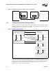
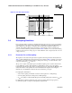
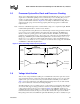
Figure 4. PLL Filter Specification
0.2 dB
0 dB
-0.5 dB
Forbidden
Zone
Forbidden
Zone
-40 dB
-28 dB
DC fpeak 1 MHz 66 MHz force