
Intel Celeron Processor for the PGA370 Socket up to 1.40 GHz on 0.13 Micron Process Datasheet

Datasheet 27
Intel
®
Celeron
®
Processor for PGA370 up to 1.40 GHz on 0.13 µ Process
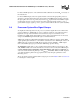
NOTES:
1. Unless otherwise noted, all specifications in this table apply to all processor frequencies.
2. All specifications in this table apply only to the Celeron processor based on 0.13 micron process core.
3. Vcc
CORE
and Icc
CORE
supply the processor core and the on-die L2 cache.
4. V
TT must be held to 1.25 V ±9% while the AGTL bus is active. It is required that VTT be held to 1.25 V ±3%
while the processor system bus is static (idle condition). The ±3% range is the required design target; ±9%
will come from the transient noise added. This is measured at the PGA370 socket pins on the bottom side of
the baseboard.
5.
These are the tolerance requirements, across a 20 MHz frequency bandwidth, measured at the
processor socket pin on the soldered-side of the motherboard.
VCC
CORE
must return to within the static
voltage specification within 100
µs after a transient event; see the VRM 8.5 DC-DC Converter Design
Guidelines
for further details.
6. Maximum I
CC is measured at VCC typical voltage and under a maximum signal loading conditions.
7. The current specified is also for AutoHALT state.
8. Maximum values are specified by design/characterization at nominal Vcc
CORE
.
9. Based on simulation and averaged over the duration of any change in current. Use to compute the maximum
inductance tolerable and reaction time of the voltage regulator. This parameter is not tested.
10. dIcc/dt specifications are measured and specified at the PGA370 socket pins.
11. Static voltage regulation includes: DC output initial voltage set point adjust, Output ripple and noise, Output
load ranges specified in the tables above. See VRM 8.5 Specification.
12.Pull ups only.
13. For frequencies beyond 1.40 GHz, refer to the latest flexible motherboard 1 extended (FMB1-E) guidelines
available via your Intel Representative.
14. 1.20 GHz at Vcc
CORE
= 1.475 volts and S-Spec number SL5XS.
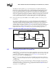
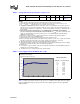
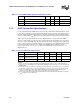
Table 8 contains typical slew rate data for the processor. Actual slew rate values and wave-shapes
may vary slightly depending on the type and size of decoupling capacitors used in a particular
implementation.
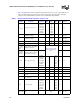
dI
v
TT
/dt
Termination current slew
rate
Table
13
A/µs
8, 9, 10 See
Table 13
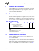
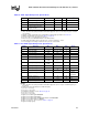
Table 7. Voltage and Current Specifications (Sheet 2 of 2)
Symbol Parameter Core Freq Min Typ Max Unit Notes
1, 2
Table 8. Power Supply Current Slew Rate (dIcc
core
/dt)
0
5
10
15
20
25
30
0123456
ICC
@
soc
k
e
t
(A)
Slew Rate: 26 A Load Step
Slew Rate (26 A): ICC at Socket
Time (us) ICC at Socket (A)
0.1 26.23
0.15 23.18
0.5 20.03
1 21.10
1.5 21.88
2 22.29
2.5 22.30
4 22.07
3.5 21.78
4 21.58
4.5 21.51
PWL SLew Rate Data