
Intel Celeron Processor for the PGA370 Socket up to 1.40 GHz on 0.13 Micron Process Datasheet


Datasheet 51
Intel
®
Celeron
®
Processor for PGA370 up to 1.40 GHz on 0.13 µ Process
4.0 Thermal Specifications and Design Considerations
This chapter provides needed data for designing a thermal solution. However, for the correct
thermal measuring processes, refer to Intel
®
Pentium
®
III Processor in the FC-PGA2, 370-pin
Package Thermal Design Guidelines (Order Number 249660). The processor uses flip chip pin
grid array packaging technology with a Integrated Heat Spreader and has a case temperature (T
case
)
specified.
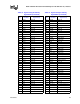
4.1 Thermal Specifications
Table 30 provides the thermal design power dissipation and maximum temperatures for the
processor. Systems should design for the highest possible processor power, even if a processor with
a lower thermal dissipation is planned. A thermal solution should be designed to ensure the case
temperature never exceeds these specifications.
1. These values are specified at nominal VCC
CORE
for the processor pins.
2. Processor power includes the power dissipated by the processor core, the L2 cache, and the AGTL bus
termination. The maximum power for each of these components does not occur simultaneously.
3. Processor core power includes only the power dissipated by the core die.
4. For frequencies beyond 1.4 GHz, refer to the latest flexible motherboard 1 extended (FMB1-E) guidelines
available via your Intel Representative.
5. 1.20 GHz at Vcc
CORE
= 1.475 volts and S-Spec number SL5XS.
4.1.1 THERMTRIP# Requirement
In the event the processor drives the THERMTRIP# signal active during valid operation, both the
V
CC and VTT supplies to the processor must be turned off to prevent thermal runaway of the
processor. Valid operation refers to the operating conditions where the THERMTRIP# signal is
guaranteed valid. The time required from THERMTRIP# asserted to V
CC rail at 1/2 nominal is 5 s
and THERMTRIP# asserted to V
TT rail at 1/2 nominal is 5 s.
NOTE: Once VCC and VTT supplies are turned off the THERMTRIP# signal will be deactivated. System logic
should ensure no “unsafe” power cycling occurs due to this deassertion.
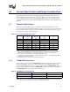
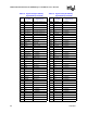
Table 30. Processor Thermal Design Power
1
Processor
Processor Core
Frequency
L2 Cache Size
(Kbytes)
Processor Power
2
(W)
Maximum T
CASE
(°C)
1.40
4
1.40 256 34.8 72
1.30
4
1.30 GHz 256 33.4 71
1.20 1.20 GHz 256 32.1 70
1.20
5
1.20 GHz 256 29.9 69
1.10A 1.10A GHz 256 28.9 69
1A 1A GHz 256 27.8 69
900 900 MHz 256 26.3 69
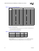
Table 31. THERMTRIP# Time Requirement
Power Rail Power Target Time Required for Power Drop
VCC 1/2 Nominal VCC 5 seconds
V
TT 1/2 Nominal VTT 5 seconds