
Intel Celeron Processor for the PGA370 Socket up to 1.40 GHz on 0.13 Micron Process Datasheet

80 Datasheet
Intel
®
Celeron
®
Processor for PGA370 up to 1.40 GHz on 0.13 µ Process
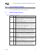
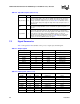
7.2 Signal Summaries
Table 41 through Table 44 list attributes of the processor output, input, and I/O signals.
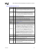
VID [3:0,25mV] O
The VID[3:0, 25 mV] (Voltage ID) pins can be used to support automatic selection
of power supply voltages. These pins are CMOS signals that must be pulled up to
3.3 V power rail with 1 K
Ω resistors. The VID pins are needed to cleanly support
voltage specification variations on processors. See Table 3 for definitions of these
pins. The power supply must supply the voltage that is requested by these pins, or
disable itself.
V
REF
I
The V
REF
input pins supply the AGTL reference voltage, which is typically 2/3 of
V
TT. V
REF
is used by the AGTL receivers to determine if a signal is a logical 0 or a
logical 1.
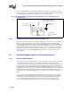
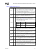
VTT_PWRGD I
The VTT_PWRGD signal informs the system that the VID/BSEL signals are in their
correct logic state. During Power-up, the VID signals will be in an indeterminate
state for a small period of time. The voltage regulator or the VRM should not sample
and/or latch the VID signals until the VTT_PWRGD signal is asserted. The
assertion of the VTT_PWRGD signal indicates the VID signals are stable and are
driven to the final state by the processor. Refer to Figure 6 for power-up timing
sequence for the VTT_PWRGD and the VID signals
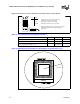
Table 40. Signal Description (Sheet 8 of 8)
Name Type Description
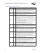
Table 41. Output Signals
Name Active Level Clock Signal Group
BSEL[1:0] High Asynch Power/Other
CPUPRES# Low Asynch Power/Other
DETECT High Asynch Power/Other
FERR# Low Asynch CMOS Output
IERR# Low Asynch CMOS Output
PRDY# Low BCLK AGTL Output
TDO High TCK TAP Output
THERMTRIP# Low Asynch CMOS Output
VID[3:0, 25mV] N/A Asynch Power/Other
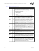
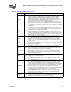
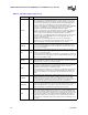
Table 42. Input Signals (Sheet 1 of 2)
Name Active Level Clock Signal Group Qualified
A20M# Low Asynch CMOS Input Always
1
BCLK High — System Bus Clock Always
BPRI# Low BCLK AGTL Input Always
DEFER# Low BCLK AGTL Input Always
FLUSH# Low Asynch CMOS Input Always
1
IGNNE# Low Asynch CMOS Input Always
1
INIT# Low Asynch CMOS Input Always
1
INTR High Asynch CMOS Input APIC disabled mode
KEY N/A Asynch Power/Other