
Intel Celeron Processor on 0.13 Micron Process in the 478-Pin Package Datasheet

16 Intel
®
Celeron
®
Processor on 0.13 Micron Process in the 478-Pin Package Datasheet
Electrical Specifications
2.4.1 Phase Lock Loop (PLL) Power and Filter
VCCA and VCCIOPLL are power sources required by the PLL clock generators on the Celeron
processor on 0.13 micron process. Since these PLLs are analog in nature, they require quiet power
supplies for minimum jitter. Jitter is detrimental to the system—it degrades external I/O timings, as
well as internal core timings (i.e., maximum frequency). To prevent this degradation, these supplies
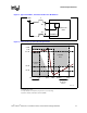
must be low pass filtered from VCC. A typical filter topology is shown in Figure 2.
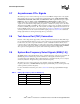
The AC low-pass requirements, with input at VCC and output measured across the capacitor
(C
A
or C
IO
in Figure 2), is as follows:
• < 0.2 dB gain in pass band
• < 0.5 dB attenuation in pass band < 1 Hz
• > 34 dB attenuation from 1 MHz to 66 MHz
• > 28 dB attenuation from 66 MHz to core frequency
The filter requirements are illustrated in Figure 3. For recommendations on implementing the filter,
refer to the appropriate Platform Design Guide listed in Table 1.
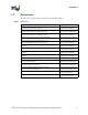
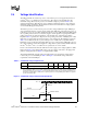
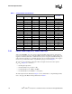
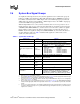
Table 3. Voltage Identification Definition
Processor Pins
Vcc_max
VID4 VID3 VID2 VID1 VID0
1 1 1 1 1 VRM output off
1 1 1 1 0 1.100
1 1 1 0 1 1.125
1 1 1 0 0 1.150
1 1 0 1 1 1.175
1 1 0 1 0 1.200
1 1 0 0 1 1.225
1 1 0 0 0 1.250
1 0 1 1 1 1.275
1 0 1 1 0 1.300
1 0 1 0 1 1.325
1 0 1 0 0 1.350
1 0 0 1 1 1.375
1 0 0 1 0 1.400
1 0 0 0 1 1.425
1 0 0 0 0 1.450
0 1 1 1 1 1.475
0 1 1 1 0 1.500
0 1 1 0 1 1.525
0 1 1 0 0 1.550