
Intel Core2 Duo Desktop Processor, Intel Pentium Processor, and Intel Pentium 4 Processor 6x1 Sequence

Case Temperature Reference Metrology
104 Thermal and Mechanical Design Guidelines
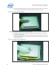
34. Clean IHS surface with IPA and a wipe.
35. Clean the LGA pads with IPA and a wipe.
36. Replace the land side cover on the device.
37. Perform a final continuity test.
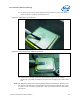
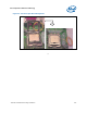
38. Wind the thermocouple wire into loops and secure or if provided by the vendor
back onto the plastic roll. (
Figure 59)
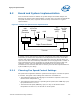
Figure 59. Finished Thermocouple Installation
39. Place the device in a tray or bag until it’s ready to be used for thermal testing use.
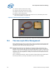
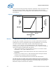
D.6 Thermocouple Wire Management
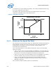
When installing the processor into the socket, make sure that the thermocouple wires
exit above the load plate as
Figure 60. Pinching the thermocouple wires between the
load plate and the IHS will likely damage the wires.
Note: When thermocouple wires are damaged, the resulting reading maybe wrong. For
example, if there are any cuts into the wires insulation where the wires are pinched
between the IHS and the load plate, the thermocouple wires can get in contact at this
location. In that case, the reported temperature would be the edge of the IHS/socket
load plate area. This temperature is usually much lower than the temperature at the
center of the IHS.
Prior to installing the heatsink, make sure that the thermocouple wires remain below
the IHS top surface, by running a flat blade on top of the IHS for example.