
Intel Core2 Duo Desktop Processor, Intel Pentium Processor, and Intel Pentium 4 Processor 6x1 Sequence

Legacy Fan Speed Control
110 Thermal and Mechanical Design Guidelines
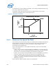
These are the minimum parameters required to implement acoustic fan speed control.
See
Figure 63 for an example. There may be vendor specific options that offer
enhanced functionality. See the appropriate vendor datasheet on how to implement
those features.
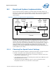
Figure 63. Fan Speed Control
Diode Temperature
(°C)
T
CONTROL
Min Speed
Fan Speed
(RPM)
Full Speed
T
LOW
X %
Fan Speed
(% PWM Duty Cycle)
100 %
Diode Temperature
(°C)
T
CONTROL
Min Speed
Fan Speed
(RPM)
Full Speed
T
LOW
X %
Fan Speed
(% PWM Duty Cycle)
100 %
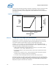
E.2.1.1 Temperature to Begin Fan Acceleration
The first item to consider is the value for T
LOW
. The FSC device needs a minimum
temperature to set as the threshold to begin increasing PWM duty cycle to the fan.
The system designer might initially consider a small temperature range
(T
CONTROL
– T
LOW
= T
RANGE
), 5 °C to accelerate the fan. That would delay the fan
accelerating for the longest time after an increase in T
SENSOR
. There are a number of
issues that should be considered with this strategy
• There is little granularity in the fan speeds. For each 1°C of increase in diode
temperature = 20% jump in PWM duty cycle %
• Fan speed oscillation as the thermal solution chases the on-die thermal sensor
temperature
• Having T
SENSOR
overshoot T
CONTROL
and the thermal profile causing the Thermal
Control Circuit to activate to reduce the temperature.
• In extreme cases Thermtrip# activates and shuts down the processor
The first two cases can create a poor acoustic response for the user. The third case
the user could notice a drop in performance as the thermal control circuit reduces the
power.
Figure 64 is an example of this situation. The system begins at idle and the
Maxpower program is started at 65% workload.