
Intel Core2 Duo Desktop Processor, Intel Pentium Processor, and Intel Pentium 4 Processor 6x1 Sequence

Legacy Fan Speed Control
Thermal and Mechanical Design Guidelines 113
E.3 Combining Thermistor and Digital Thermal
Sensor Control
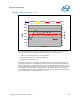
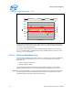
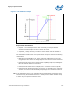
There is no closed loop control between the FSC and the thermistor, but they work in
tandem to provide the maximum fan speed reduction. As discussed in Section
E.1.1,
the thermistor establishes the VSF curve. This curve determines the maximum fan
speed as a function of the ambient temperature and by design provides a Ψ
CA
sufficient to meet the thermal profile. The FSC, by measuring the processor on-die
thermal sensor will command the fan to reduce speed below the VSF curve in
response to processor workload. Conversely, if the processor workload increases, the
FSC will command the fan via the PWM duty cycle to accelerate the fan up to the limit
imposed by the VSF curve.
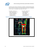
Figure 66. On-Die Thermal Sensor and Thermistor
Fan Speed
(RPM)
Inlet Temperature (°C)
Full
Speed
30
38
Min.
Operating
Variable Speed Fan (VSF) Curve
Fan Speed
Operating Range
with FSC
34
Min %
Fan Speed
(% PWM Duty Cycle)
100 %
Fan Speed
(RPM)
Inlet Temperature (°C)
Full
Speed
30
38
Min.
Operating
Variable Speed Fan (VSF) Curve
Fan Speed
Operating Range
with FSC
34
Min %
Fan Speed
(% PWM Duty Cycle)
100 %
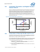
E.4 Interaction of Thermal Profile and T
CONTROL
The processor thermal specification is comprised of the two parameters, T
CONTROL
and
Thermal Profile. The minimum requirement for thermal compliance is to ensure the
thermal solution, by design, meets the thermal profile.
If the system design incorporates acoustic speed fan control, Intel requires monitoring
the on-die thermal sensor to implement acoustic fan speed control. The value of the
on-die thermal sensor temperature determines which specification must be met.
• On-die Thermal Sensor less than T
CONTROL
⎯ When the thermal solution can maintain the thermal sensor temperature to
less than T
CONTROL
then the fan speed can be reduced.
• On-die Thermal Sensor greater than T
CONTROL
⎯ The T
C
must be maintained at or below the Thermal Profile for the measured
power dissipation.