
Intel Core2 Duo Desktop Processor, Intel Pentium Processor, and Intel Pentium 4 Processor 6x1 Sequence

Mechanical Drawings
Thermal and Mechanical Design Guidelines 123
Appendix G Mechanical Drawings
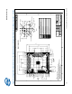
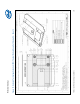
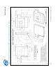
The following table lists the mechanical drawings included in this appendix. These
drawings refer to the reference thermal mechanical enabling components for the
processor.
Note: Intel reserves the right to make changes and modifications to the design as
necessary.
Drawing Description Page Number
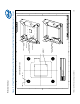
ATX/µATX Motherboard Keep-out Footprint Definition and Height
Restrictions for Enabling Components – Sheet 1
124
ATX/µATX Motherboard Keep-out Footprint Definition and Height
Restrictions for Enabling Components – Sheet 2
125
ATX/µATX Motherboard Keep-out Footprint Definition and Height
Restrictions for Enabling Components – Sheet 3
126
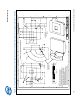
. Balanced Technology Extended (BTX) Thermal Module Keep Out
Volumetric – Sheet 1
127
Balanced Technology Extended (BTX) Thermal Module Keep Out
Volumetric – Sheet 2
128
. Balanced Technology Extended (BTX) Thermal Module Keep Out
Volumetric – Sheet 3
129
Balanced Technology Extended (BTX) Thermal Module Keep Out
Volumetric – Sheet 4
130
Balanced Technology Extended (BTX) Thermal Module Keep Out
Volumetric – Sheet 5
131
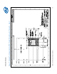
ATX Reference Clip – Sheet 1 132
ATX Reference Clip – Sheet 2 133
Reference Fastener – Sheet 1 134
Reference Fastener – Sheet 2 135
Reference Fastener – Sheet 3 136
Reference Fastener – Sheet 4 137
Intel
®
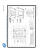
RCFH4 Reference Solution Assembly 138
Intel® RCFH4 Reference Solution Assembly – Sheet 2 139