
Intel Core2 Duo Desktop Processor, Intel Pentium Processor, and Intel Pentium 4 Processor 6x1 Sequence

Intel® Enabled Balanced Technology Extended (BTX) Reference solution
Thermal and Mechanical Design Guidelines 43
3. Acoustics testing for Case 2 will be system level in the same a BTX S2 reference chassis
and commercially available power supply. Acoustic data for Case 2 will be provided in
the validation report but this condition is not a target for the design. The acoustic model
is predicting that the power supply fan will be the acoustic limiter.
4. The fan speeds (RPM) are estimates for one of the two reference fans and will be
adjusted to meet thermal performance targets then acoustic target during validation.
The designer should identify the fan speed required to meet the effective fan curve
shown in Section
5.1.3
5. Minimum fan speed is expected to be no higher than 1200 RPM for the fan being used
in validation testing.
While the fan hub thermistor helps optimize acoustics at high processor workloads by
adapting the maximum fan speed to support the processor thermal profile, additional
acoustic improvements can be achieved at lower processor workload by using the
T
CONTROL
specifications described in Section 2.2.3. Intel’s recommendation is to use the
Fan Specification for 4 Wire PWM Controlled Fans to implement fan speed control
capability based the digital thermal sensor. Refer to Chapter
7 for further details.
5.1.3 Effective Fan Curve
The TMA must fulfill the processor cooling requirements shown in Table 3 when it is
installed in a functional BTX system. When installed in a system, the TMA must
operate against the backpressure created by the chassis impedance (due to vents,
bezel, peripherals, etc…) and will operate at lower net airflow than if it were tested
outside of the system on a bench top or open air environment. Therefore an allowance
must be made to accommodate or predict the reduction in Thermal Module
performance due to the reduction in heatsink airflow from chassis impedance. For this
reason, it is required that the Thermal Module satisfy the prescribed Ψ
CA
requirements
when operating against an impedance that is characteristic for BTX platforms.
Because of the coupling between TMA thermal performance and system impedance,
the designer should understand the TMA effective fan curve. This effective fan curve
represents the performance of the fan component AND the impedance of the stator,
heatsink, duct, and flow partitioning devices. The BTX system integrator will be able to
evaluate a TMA based on the effective fan curve of the assembly and the airflow
impedance of their target system.
Note: It is likely that at some operating points the fans speed will be driven by the system
airflow requirements and not the processor thermal limits.
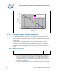
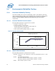
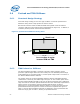
Figure 10 shows the effective fan curve for the reference design TMA. These curves
are based on analysis. The boundary conditions used are the S2 6.9L reference
chassis, the reference TMA with the flow portioning device, extrusion and an AVC Type
II fan geometry.
When selecting a fan for use in the TMA care should be taken that similar effective fan
curves can be achieved. Final verification requires the overlay of the Type II MASI
curve to ensure thermal compliance.