
Intel Core2 Duo Desktop Processor, Intel Pentium Processor, and Intel Pentium 4 Processor 6x1 Sequence

Intel® Enabled Balanced Technology Extended (BTX) Reference solution
50 Thermal and Mechanical Design Guidelines
5.6 Preload and TMA Stiffness
5.6.1 Structural Design Strategy
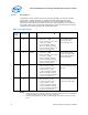
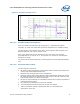
Structural design strategy for the Intel Type II TMA is to minimize upward board
deflection during shock to help protect the LGA775 socket.
BTX thermal solutions utilize the SRM and TMA that together resists local board
curvature under the socket and minimize, board deflection (
Figure 14). In addition, a
moderate preload provides initial downward deflection.
Figure 14. Upward Board Deflection During Shock
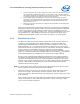
5.6.2 TMA Preload vs. Stiffness
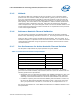
The Thermal Module assembly is required to provide a static preload to ensure
protection against fatigue failure of socket solder joint. The allowable preload range
for BTX platforms is provided in
Table 7, but the specific target value is a function of
the Thermal Module effective stiffness.
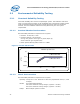
The solution space for the Thermal Module effective stiffness and applied preload
combinations is shown by the shaded region of
Figure 15. This solution space shows
that the Thermal Module assembly must have an effective stiffness that is sufficiently
large such that the minimum preload determined from the relationship requirement in
Figure 15 does not exceed the maximum allowed preload shown in Table 7.
Furthermore, if the Thermal Module effective stiffness is so large that the minimum
preload determined from
Figure 15 is below the minimum required value given in
Table 7, then the Thermal Module should be re-designed to have a preload that lies
within the range given in
Table 7, allowing for preload tolerances.
Less curvature in region
between SRM and TMA
Shock Load