
Intel Core2 Duo Desktop Processor, Intel Pentium Processor, and Intel Pentium 4 Processor 6x1 Sequence

Intel® Enabled Balanced Technology Extended (BTX) Reference solution
52 Thermal and Mechanical Design Guidelines
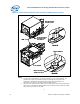
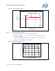
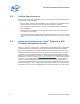
Figure 16. Thermal Module Attach Pointes and Duct-to-SRM Interface Features
SRM
Fro nt attach point
use 6x32 screw
See detail A
Detail A
See detail B
Detail B
Rear attach point
use 6x32 screw
Chassis PEM nut
Duct front interface
feature see note 2
SRM
Fro nt attach point
use 6x32 screw
See detail A
Detail A
See detail B
Detail B
Rear attach point
use 6x32 screw
Chassis PEM nut
Duct front interface
feature see note 2
NOTE:
1. For clarity the motherboard is not shown in this figure. In an actual assembly, the
captive 6x32 screws in the thermal module pass through the rear holes in the
motherboard designated in the socket keep-in
Figure 73 through Figure 77 in
Appendix G and screw into the SRM and chassis PEM features.
2. This front duct ramp feature has both outer and inner lead-in that allows the feature to
slide easily into the SRM slot and around the chassis PEM nut. Note that the front PEM
nut is part of the chassis not the SRM.
§