
Intel Core2 Duo Desktop Processor, Intel Pentium Processor, and Intel Pentium 4 Processor 6x1 Sequence

ATX Thermal/Mechanical Design Information
62 Thermal and Mechanical Design Guidelines
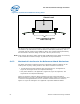
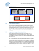
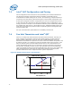
Figure 20. Upward Board Deflection During Shock
The target metal clip nominal stiffness is 540 N/mm [3100 lb/in]. The combined target
for reference clip and fasteners nominal stiffness is 380 N/mm [2180 lb/in]. This is
consistent with the results for the RCBFH-3 design. The nominal preload provided by
the Intel RCFH-4 reference design is 191.3 N ± 44.5 N [43 lb ± 10 lb].
Note: Intel reserves the right to make changes and modifications to the design as necessary
to the Intel RCFH-4 reference design, in particular the clip and fastener.
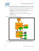
6.6.2 Mechanical Interface to the Reference Attach Mechanism
The attach mechanism component from the Intel RCFH-4 Reference Design can be
used by other 3
rd
party cooling solutions. The attach mechanism consists of:
• A metal attach clip that interfaces with the heatsink core; see Appendix G,
Figure 78, and Figure 79 for the component drawings.
• Four plastic fasteners; see Appendix G, Figure 80, Figure 81, Figure 82, and
Figure 83 for the component drawings.
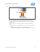
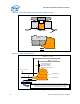
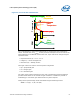
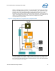
Figure 19 shows the reference attach mechanism as part of the Intel RCFH-4
Reference Design. The clip is assembled to heatsink during copper core insertion, and
is meant to be trapped between the core shoulder and the extrusion as shown in
Figure 21. Figure 78 and Figure 79 in Appendix G provides additional details.
Less curvature in region
under stiff clip
Shock Load