
Intel Core2 Duo Desktop Processor, Intel Pentium Processor, and Intel Pentium 4 Processor 6x1 Sequence
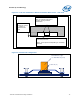

LGA775 Socket Heatsink Loading
72 Thermal and Mechanical Design Guidelines
Simulation shows that the solder joint force (F
axial
) is proportional to the board
deflection measured along the socket diagonal. The matching of F
axial
required to
protect the LGA775 socket solder joint in temperature cycling is equivalent to
matching a target MB deflection.
Therefore, the heatsink preload for LGA775 socket solder joint protection against
fatigue failure can be more generally defined as the load required to create a target
board downward deflection throughout the life of the product
This board deflection metric provides guidance for mechanical designs that differ from
the reference design for ATX//µATX form factor.
A.2.2 Motherboard Deflection Metric Definition
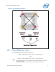
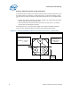
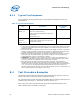
Motherboard deflection is measured along either diagonal (refer to Figure 29):
d = dmax – (d1 + d2)/2
d’ = dmax – (d’1 + d’2)/2
Configurations in which the deflection is measured are defined in Table 11.
To measure board deflection, follow industry standard procedures (such as IPC) for
board deflection measurement. Height gauges, and possibly dial gauges may also be
used.
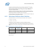
Table 11. Board Deflection Configuration Definitions
Configuration
Parameter
Processor + Socket
load plate
Heatsink Parameter Name
d_ref yes no BOL deflection, no preload
d_BOL yes yes BOL deflection with
preload
d_EOL yes yes EOL deflection
BOL: Beginning of Life
EOL: End of Life