
Intel Core2 Duo Desktop Processor, Intel Pentium Processor, and Intel Pentium 4 Processor 6x1 Sequence

Heatsink Clip Load Metrology
Thermal and Mechanical Design Guidelines 77
Appendix B Heatsink Clip Load
Metrology
B.1 Overview
This section describes a procedure for measuring the load applied by the
heatsink/clip/fastener assembly on a processor package.
This procedure is recommended to verify the preload is within the design target range
for a design, and in different situations. For example:
• Heatsink preload for the LGA775 socket
• Quantify preload degradation under bake conditions.
Note: This document reflects the current metrology used by Intel. Intel is continuously
exploring new ways to improve metrology. Updates will be provided later as this
document is revised as appropriate.
B.2 Test Preparation
B.2.1 Heatsink Preparation
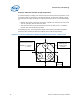
Three load cells are assembled into the base of the heatsink under test, in the area
interfacing with the processor Integrated Heat Spreader (IHS), using load cells
equivalent to those listed in Section B.2.2.
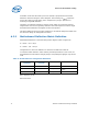
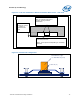
To install the load cells, machine a pocket in the heatsink base, as shown Figure 31
and
Figure 32. The load cells should be distributed evenly, as close as possible to the
pocket walls. Apply wax around the circumference of each load cell and the surface of
the pocket around each cell to maintain the load cells in place during the heatsink
installation on the processor and motherboard (Refer to
Figure 32).
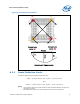
The depth of the pocket depends on the height of the load cell used for the test. It is
necessary that the load cells protrude out of the heatsink base. However, this
protrusion should be kept minimal, as it will create additional load by artificially
raising the heatsink base. The measurement offset depends on the whole assembly
stiffness (i.e., motherboard, clip, fastener, etc.). For example, the Intel RCFH-4
Reference Heatsink Design clip and fasteners assembly stiffness is expected to be
similar to the RCBFH-3 or around 380 N/mm [2180 lb/in]. Final values will be
published after design validation. In that case, a protrusion of 0.038 mm [0.0015”]
will create an extra load of 15 N [3.3 lb].
Figure 33 shows an example using the Intel
RCFH-4 Reference Heatsink.
Note: When optimizing the heatsink pocket depth, the variation of the load cell height
should also be taken into account to make sure that all load cells protrude equally
from the heatsink base. It may be useful to screen the load cells prior to installation to
minimize variation.