
Intel Core2 Duo Desktop Processor, Intel Pentium Processor, and Intel Pentium 4 Processor 6x1 Sequence


Case Temperature Reference Metrology
90 Thermal and Mechanical Design Guidelines
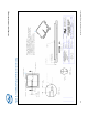
The orientation of the groove relative to the package pin 1 indicator (gold triangle in
one corner of the package) is shown in
Figure 37 for the 775-Land LGA package IHS.
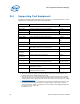
Figure 37. IHS Groove per Figure 35 on the 775-LAND LGA Package
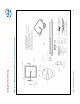
When the processor is installed in the LGA775 socket, the groove is perpendicular to
the socket load lever, and on the opposite side of the lever, as shown
Figure 38.
Figure 38. IHS Groove per Figure 35 Orientation Relative to the LGA775 Socket
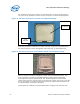
Select a machine shop that is capable of holding drawing specified tolerances. IHS
groove geometry is critical for repeatable placement of the thermocouple bead,
ensuring precise thermal measurements. The specified dimensions minimize the
impact of the groove on the IHS under the socket load. A larger groove may cause the
IHS to warp under the socket load such that it does not represent the performance of
an ungrooved IHS on production packages.
Inspect parts for compliance to specifications before accepting from machine shop.
Pin1
indicator
IHS Groove