
Intel Core2 Duo Desktop Processor, Intel Pentium Processor, and Intel Pentium 4 Processor 6x1 Sequence


Case Temperature Reference Metrology
Thermal and Mechanical Design Guidelines 95
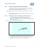
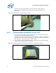
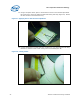
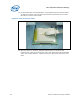
Figure 45. Third Tape Installation
12. Place a 3
rd
piece of tape at the end of the step in the groove as shown in
Figure 45. This tape will create a solder dam to prevent solder from flowing into
the larger IHS groove section during the melting process.
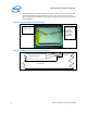
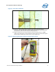
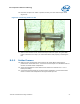
13. Measure resistance from thermocouple end wires (hold both wires to a DMM
probe) to the IHS surface. This should be the same value as measured during the
thermocouple conditioning in Section
D.5.1.step 3 (Figure 46)
Figure 46. Measuring Resistance between Thermocouple and IHS