
Intel Core2 Duo Desktop Processor, Intel Pentium Processor, and Intel Pentium 4 Processor 6x1 Sequence


Case Temperature Reference Metrology
Thermal and Mechanical Design Guidelines 97
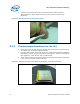
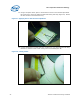
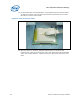
16. Place the two pieces of solder in parallel, directly over the thermocouple bead
(
Figure 49)
Figure 49. Positioning Solder on IHS
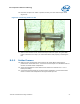
17. Measure the resistance from the thermocouple end wires again using the DMM
(refer to Section
D.5.1.step 2) to ensure the bead is still properly contacting the
IHS.
D.5.3 Solder Process
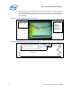
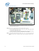
18. Make sure the thermocouple that monitors the Solder Block temperature is
positioned on the Heater block. Connect the thermocouple to a handheld meter to
monitor the heater block temperature
19. Verify the temperature of the Heater block station has reached 155 °C ±5 °C
before proceeding.
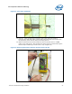
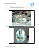
20. Connect the thermocouple for the device being soldered to a second hand-held
meter to monitor IHS temperature during the solder process.