
Note


Application Note 17
5 Board Design Impact on Test
Results
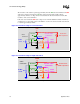
After the production of Intel
®
Socket Test Technology for LGA771 had begun, changes were made
to board design around the processor socket that will impact test results. These changes affect four
pins—A24, E29, G1, and U1—that were connected to the VSS (Ground) plane in the original
board design. The pins are still in the GND column of the Ball Usage tables in Section 7, but they
have been high-lighted in grey to call attention to the change.
Since the change affects particular boards, it is recommended that each design be reviewed to
determine if any or all of these pins are used as signals or VSS.
5.1 How to Test
If the pins are used as signals rather than ground or power, possible techniques to keep test results
the same include the following:
• Place test points on the pin nets and use fixture relays to connect the pins to VSS prior to
powering up the board or testing the socket using the un-powered test method. Fixture relays
that can be activated and deactivated through program control will accommodate the “Shorts”
test.
• Use test points and test head resources to put the pins at a VSS level while using the powered
or un-powered test methods.
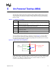
5.2 U1 Pin for Powered Testing
If U1 is a signal rather than ground, and the board under test is to be powered up, then the board
design must
include a test point on the board net for the U1 pin. In the original design, U1 was the
ground path for control pin E5. It was used to ensure that the switches defaulted to the OFF state
when power was applied or while other devices were being tested.
In designs where U1 is a signal pin, it should be tied to VSS (Ground) through fixture relays that
can be activated and deactivated through program control to accommodate the “Shorts” test. To
ensure that the switches default to OFF when power is applied or while other devices are being
tested, the control signals are pulled to ground with 1k resistors.
§