
Note


Related Specifications
20 Application Note
§
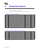
Table 6-3. Test Condition for Low Side Switch (Powered Digital)
Symbol Parameter Value Units
Vccp Applied Voltage 1.2 max V
Hcontrol Disable High Side Switch 0.0 V
Lcontrol Enable Low Side Switch 1.8 max V
Signal Maximum VOL 200 mV
Signal Load Current Source from Signal to Vccp (Pull Up) 2 mA
Signal VohTh Test VOH Threshold Setting 400 mV
Signal VolTh Test VOL Threshold Setting 400 mV
Table 6-4. Test Condition for Switch (Un-powered Analog)
Symbol Parameter Value Units
VccpToGnd Vccp Connected To Gnd 0.0 V
HctrlEn Enable High Side Switch 1.2 max V
HctrlDis Disable High Side Switch 0.0 V
LctrlEn Enable Low Side Switch 1.2 max V
LctrlDis Disable Low Side Switch 0.0 V
SigSrcVolt Signal Applied Source Voltage 600 max mV
SigSrcVR Signal Applied Source Voltage Resistance 500 Ω