
Guide

18 Intel
®
Celeron
®
D Processor for Embedded Applications Thermal Design Guide
Design Guidelines
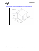
2.1.3 Heatsink Attach
There are no features on the mPGA478 socket to directly attach a heatsink; a heatsink attach
mechanism must be designed to support the heatsink. The attach mechanism has two main roles:
• To ensure thermal performance to the TIM applied between the IHS and heatsink.
• To ensure system electrical, thermal, and structural integrity under shock and vibration events.
TIMs based on phase change materials are sensitive to applied pressure; the higher the pressure, the
better the initial performance of the TIM. TIMs such as thermal greases are less sensitive to applied
pressure.
The mechanical requirements of the attach mechanism depend on the weight of the heatsink and
the level of shock and vibration that the system must support. The overall structural design of the
motherboard and the system must be considered when designing the heatsink attachment
mechanism. The design must provide a means for protecting the mPGA478 socket solder joints and
prevent package pullout from the socket.
The most widely used form of attach mechanism is a Retention Mechanism (RM) and attach clips
that secure the heatsink to the motherboard. The following sections contain more specific
guidelines for designing an attach mechanism.
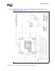
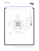
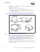
2.1.3.1 Retention Mechanism-ATX Form Factor
The thermal solution must be compatible with the Intel reference retention mechanism. Refer to
Figure 15 and Figure 16 in Appendix A, “Mechanical Drawings,” for the mechanical drawing of
the reference retention mechanism. The Intel reference retention mechanism is available for the
Intel Celeron D Processor in the FC-mPGA4 package and is also recommended for the Intel
Celeron D Processor heatsink.
Ask your Intel representative for model information in electronic format (IGES and DXF).
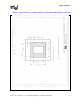
If another type of retention mechanism is developed, it must comply with the following guidelines:
• No tools required for assembly or installation to/removal from the motherboard.
• Symmetrical design allowing installation in either orientation.
• Installation force on the motherboard lower than 15 lbf.
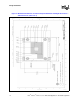
• Motherboard interface compliant with motherboard volumetric constraints, as defined in
Figure 3 through Figure 5. This includes:
— Hole pattern information
—Hole size
— Board thickness: 0.062 inches (design specific).